Combinational Circuits II
(Usage hints for this presentation)
IT Systems, Summer Term 2026
Dr.-Ing. Matthes Elstermann
1. Introduction
- Part 1
- Break for self-study
- Part 2
2. Hack ALU
2.1. ALU Design
- Arithmetic Logic Unit (ALU)
- Computes fixed set of functions
- Arithmetic functions, e.g., x + y, x - y, x + 1
- Logical functions, e.g., or(x, y), and(x, y)
- Specific function determined by control bits
- Programming the ALU means setting the control bits
- Computes fixed set of functions
2.2. Hack ALU Overview
Pins
- Two 16-bit input numbers
- One 16-bit output number
- And two output bits
- Is output zero (zr)?
- Is output negative (ng)?
- And two output bits
- Six control bits
- For \(2^6\) possible operations; 18 actually specified in (Nisan and Schocken 2005)
- Important symbols in ALU context
- Arithmetic operations: x+y, x-y, -x
- Logical operations: x&y (and), x|y (or), !x (not)
- Thus, “+” denotes addition, not the logical Or
2.3. Hack ALU Operations
- Bit-wise logical operations on 16-bit numbers, e.g.:
And16: 1010101010101010 & 0000000011111111 = 0000000010101010Not16: !1010101010101010 = 0101010101010101- Negate/invert/flip all bits
Add16: Addition of 16-bit numbers x and y (in 2’s complement)
2.4. Subtraction by Negation in ALU Context
- -x has no special meaning: -x = (-1)*x
- Using 2’s complement
!x is bit-wise negation of x (see previous slide)
- In the following, “negate” means “flip all bits”
- Fact: !x = -x - 1 (in 2’s complement)
- Proof:
- !x + x = 1…1 (all bits 1, as each bit that is 1 in x is 0 in !x and vice versa) = -1
- Subtract x on both sides
- Proof:
Fact: x - y = !(!x + y)
- Proof: !(!x + y) = -(-x - 1 + y) - 1 = x - y
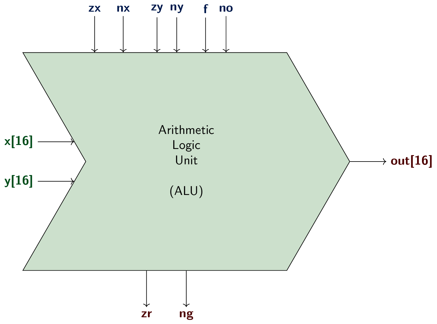
2.5. Hack ALU Chip
zx = zero   x
nx = negate x
zy = zero   y
ny = negate y
f  = apply function, either add or and
no = negate output

zr = out zero
ng = out negative
2.6. Hack ALU Specification
 * [Excerpt of ALU.hdl from Nand2Tetris]
 * Computes out = one of the following functions:
 *     0, 1, -1, x, y, !x, !y, -x, -y,
 *     x + 1, y + 1, x - 1, y - 1, x + y, x - y, y - x,
 *     x & y, x | y
 * [...]
// Implementation: Manipulates the x and y inputs
// and operates on the resulting values, as follows:
// if (zx == 1) sets x = 0        // 16-bit constant
// if (nx == 1) sets x = !x       // bitwise not
// if (zy == 1) sets y = 0        // 16-bit constant
// if (ny == 1) sets y = !y       // bitwise not
// if (f == 1)  sets out = x + y  // integer 2's complement addition
// if (f == 0)  sets out = x & y  // bitwise and
// if (no == 1) sets out = !out   // bitwise not
2.7. ALU Logic Examples
- Table in Figure 2.6 of (Nisan and Schocken 2005) documents ALU control bits
- Let us look at some rows of that table
2.7.1. Row 14, x+y
| zx | nx | zy | ny | f | no | out |
|---|---|---|---|---|---|---|
| 0 | 0 | 0 | 0 | 1 | 0 | x+y |
- zx=nx=zy=ny=0: Neither zero nor negate inputs
- f=1: Perform addition
- no=0: Do not negate output
2.7.2. Row 15, x-y
| zx | nx | zy | ny | f | no | out |
|---|---|---|---|---|---|---|
| 0 | 1 | 0 | 0 | 1 | 1 | x-y |
- As explained previously: x - y = !(!x + y)
- Thus
- zx=0, nx=1: Negate x
- zy=0, ny=0: Keep y unchanged
- f=1: Add
- no=1: Negate result
- Self-study: How to implement logical Or? (De Morgan!)
2.7.3. Row 5, y
| zx | nx | zy | ny | f | no | out |
|---|---|---|---|---|---|---|
| 1 | 1 | 0 | 0 | 0 | 0 | y |
- zx=1, nx=1: Zero, then negate x: x → 00…0 → 11…1
- zy=0, ny=0: Keep y unchanged
- f=0: Perform bit-wise And
- All 1s of zero-negated x preserve y
- no=0: Keep result
2.7.4. Row 2, 1
| zx | nx | zy | ny | f | no | out |
|---|---|---|---|---|---|---|
| 1 | 1 | 1 | 1 | 1 | 1 | 1 |
- zx=1, nx=1: Zero, then negate x: x → 00…0 → 11…1
- All bits one is -1 in 2’s complement
- zy=1, ny=1: Zero, then negate y: y → 00…0 → 11…1
- All bits one is -1 in 2’s complement
- f=1: Add
- (-1) + (-1) = -2 = 1…10
- no=1: Negate output, 0…01 = 1
2.7.5. Row 10, x+1
| zx | nx | zy | ny | f | no | out |
|---|---|---|---|---|---|---|
| 0 | 1 | 1 | 1 | 1 | 1 | x+1 |
- zx=0, nx=1: Negate x, !x
- zy=1, ny=1: Zero, then negate y, -1
- f=1: Add
- !x + (-1) = !x - 1
- Since !x = -x - 1, we have !x - 1 = -x - 1 - 1 = -x - 2
- no=1: Negate output, !(-x - 2) = -(-x - 2) - 1 = x + 1
2.7.6. Self-Study
| zx | nx | zy | ny | f | no | out |
|---|---|---|---|---|---|---|
| 0 | 1 | 0 | 1 | 1 | 1 | ? |
What operation is performed by the Hack ALU for the above control bits?
3. Project 2
- Build
- Adders, in particular
Add16 ALUInc16, an incrementer
- Adders, in particular
3.1. Notes on ALU
- What parts to use? How?
- Clearly, use
Add16,And16to implement main functions - Process x and y in parallel for zeroing and negation
- At least 2 chips
Not16
- At least 2 chips
- Use at least one
Mux16for each if statement, e.g.:- Initially, use zx:
Mux16(a=x, b=false, sel=zx, out=zeroX);- (Note next slide for
b=false)
- (Note next slide for
- Finally, use f:
Mux16 (a=xAndY, b=xPlusY, sel=f, out=xOpY);- (In between, how would you compute
xAndYandxPlusY?)
- (In between, how would you compute
- Initially, use zx:
- Clearly, use
3.2. HDL Tips
- If you need constant numbers, use
trueandfalse, e.g.:a = falseanda[0..15] = falseassign 0 toaa[0] = true, a[1..15] = falseassigns 1 toa
- You can give names to parts of a word, e.g.:
out[0..7] = outlow- Then use
outlowelsewhere as input
- The chip’s output
outcannot be used as input in the same chip- Assign new names if that should be necessary, e.g.:
out = out, out = othername- Then use
othernameelsewhere as input
- Assign new names if that should be necessary, e.g.:
4. Conclusions
4.1. Summary
- Binary adders from half and full adders
- Use 2’s complement for negative numbers and subtraction
- Ripple-carry adder for any number of bits
- Hack ALU uses 6 control bits to specify operation
- Simple operations, e.g., no multiplication
- Build it as part of Project 2!
4.2. Q&A
Bibliography
Nisan, Noam, and Shimon Schocken. 2005. The Elements of Computing Systems: Building a Modern Computer from First Principles. The MIT Press. https://www.nand2tetris.org/.
License Information
Source files are available on GitLab (check out embedded submodules) under free licenses. Icons of custom controls are by @fontawesome, released under CC BY 4.0.
Except where otherwise noted, the work “Combinational Circuits II”, © 2024-2025 Jens Lechtenbörger, is published under the Creative Commons license CC BY-SA 4.0.